A 3D building model contains a lot of useful information. Turning it into a readable document takes another kind of work: choosing views, separating stages, making room for measurements and explaining which parts belong together.
The new Create assembly guide feature gives you a starting set of pages inside Project Planner 2. It reads a supported generated building and prepares a draft containing a project specification, assembly stages, measured views and parts tables. You can add larger drawing substeps and four final elevations, then edit the result with the Planner tools you already use.
That first draft is the beginning of your document. You decide what needs explaining, check the model and add the project-specific information the generator cannot supply.
It creates ordinary, editable Planner pages from supported model parts. Your existing pages stay in place. Creating the guide does not automatically export a PDF or spend the 50 credits used by premium PDF export.
From a building model to a first draft
Start with a building you have generated in Autostrek. A simple shed is a useful first example; the supported Cabin / Shed, Double Garage, House and Sauna starters give you more to explore as you become familiar with the pages.
For this walkthrough, imagine a Double Garage with its foundation perimeter, wall framing and saved W-frame roof trusses. If you add supported rectangular windows or doors with O-framer, those openings can also be represented in the guide.
- Save a copy of the project before preparing the booklet.
- Open Project Planner 2 and choose Default View. The automatic guide starts from this view rather than an active booklet page.
- Select Create assembly guide.
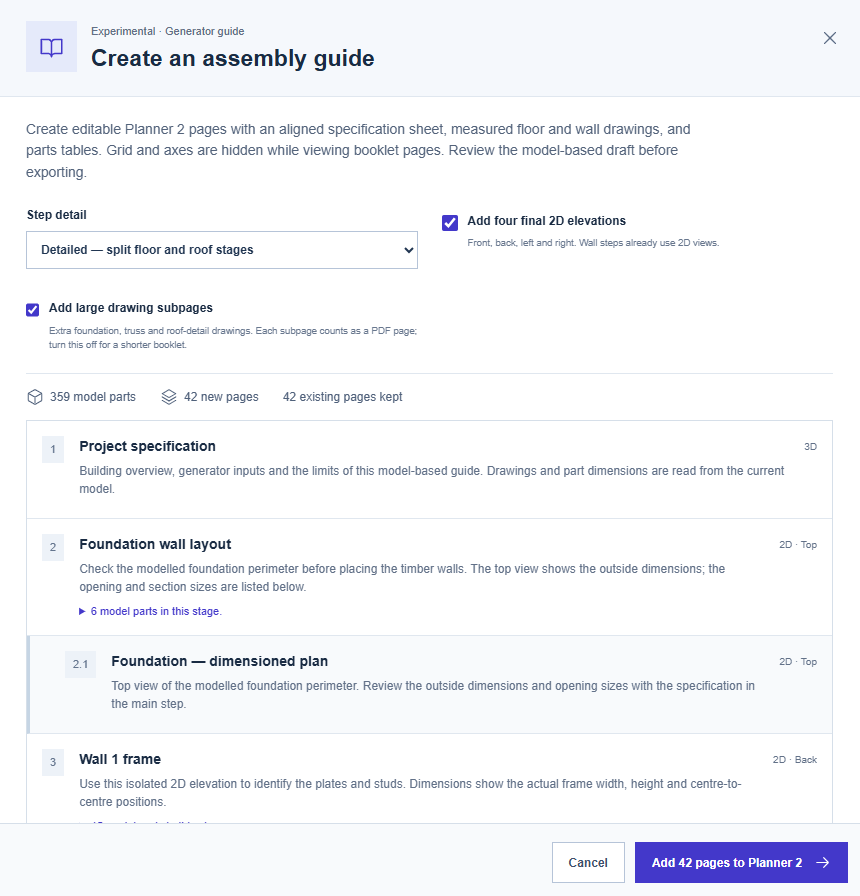
- Choose the detail level and optional drawings. Read the proposed page list and expand stages to inspect their parts.
- If the preview identifies unsupported or incomplete model data, resolve that first. When the draft is ready, choose Add pages to Planner 2.
The generated pages are added after your existing pages. Your previous notes and drawings are preserved. Generating another guide adds another set, so check the list before doing it a second time.
From model to editable booklet
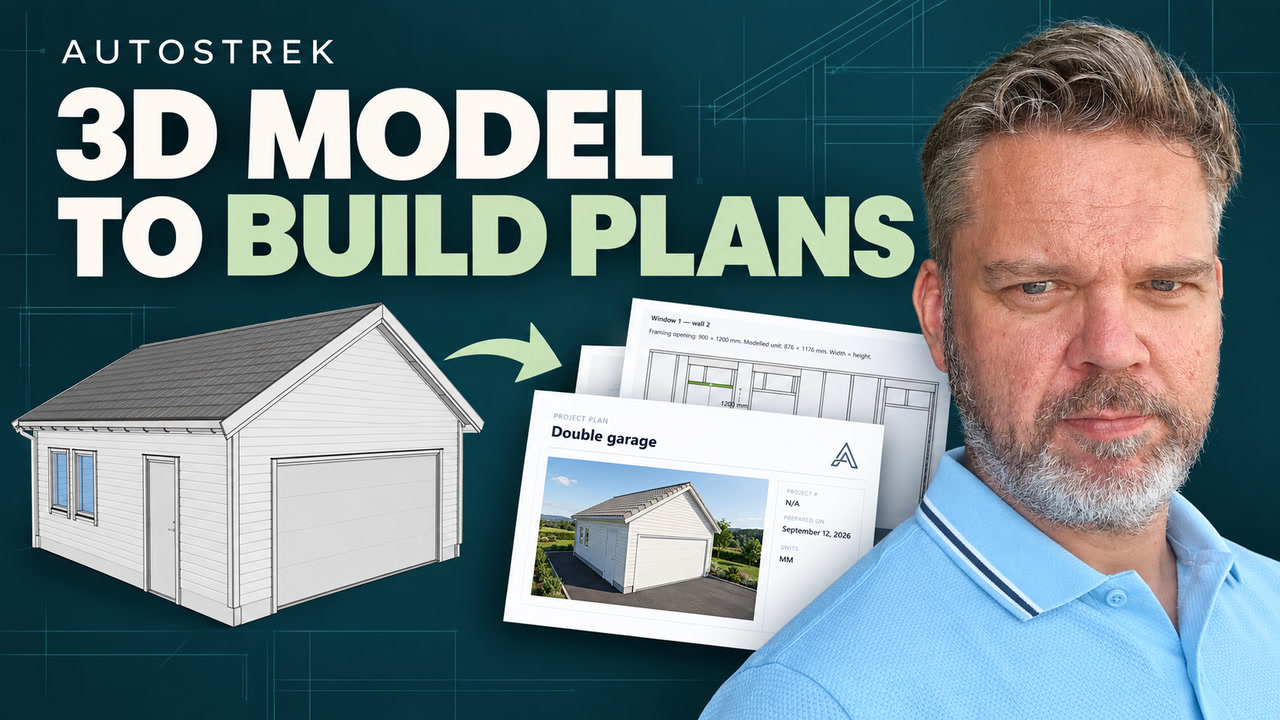
See the automatic guide in action: turn a building model into editable pages, then prepare a PDF for your own project or your customers. Follow the illustrated guide below for the detailed review and editing workflow, current limitations and export options.
Watch on YouTubeChoose what goes into the booklet
Compact groups the main building stages into a shorter document. Detailed separates more of the floor and roof work. Both use the same model; choosing a longer document does not add construction detail that was never modelled or specified.
Add large drawing subpages gives selected steps more room for illustrations and measurements. It is enabled when the guide dialog opens. Turning it off can shorten the booklet, although some essential drawings, such as a complete-truss profile, can still remain as substeps.
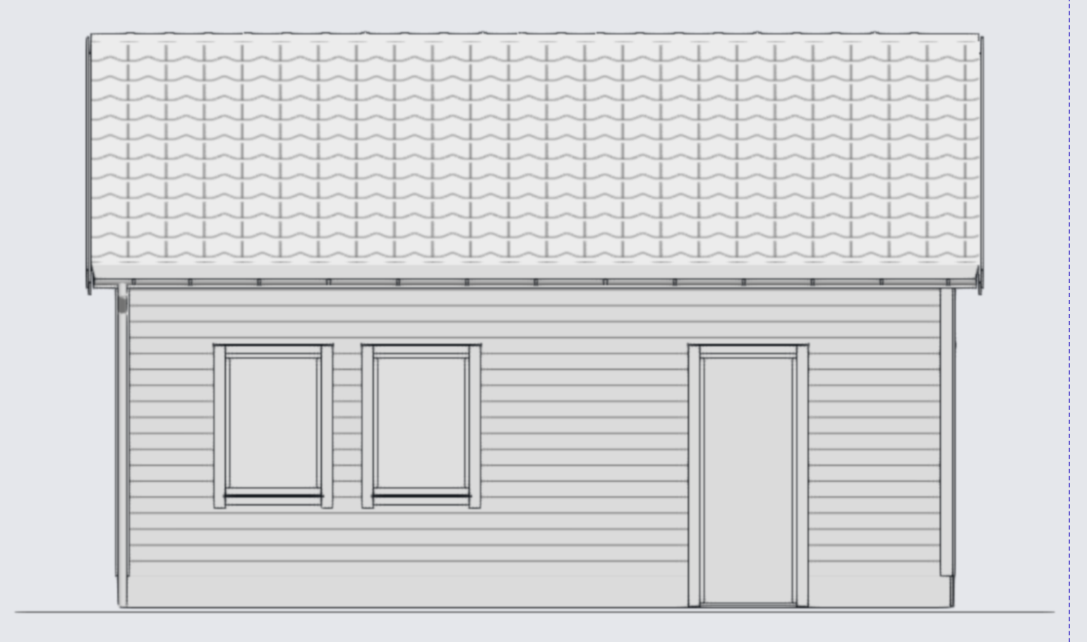
Add four final 2D elevations appends front, back, left and right views of the completed building. The wall-framing pages already have their own 2D views, so final elevations serve a different purpose: they show the finished overall form. Add and check any dimensions you need on these final elevations; they do not arrive with a complete automatic dimension set.
The preview shows the proposed pages and an estimated PDF total that includes the cover and your existing pages. The final export dialog also counts any selected appendices. Use those totals for your project; page counts change with the model and the options you choose.
What the generated pages explain
Begin with the project specification
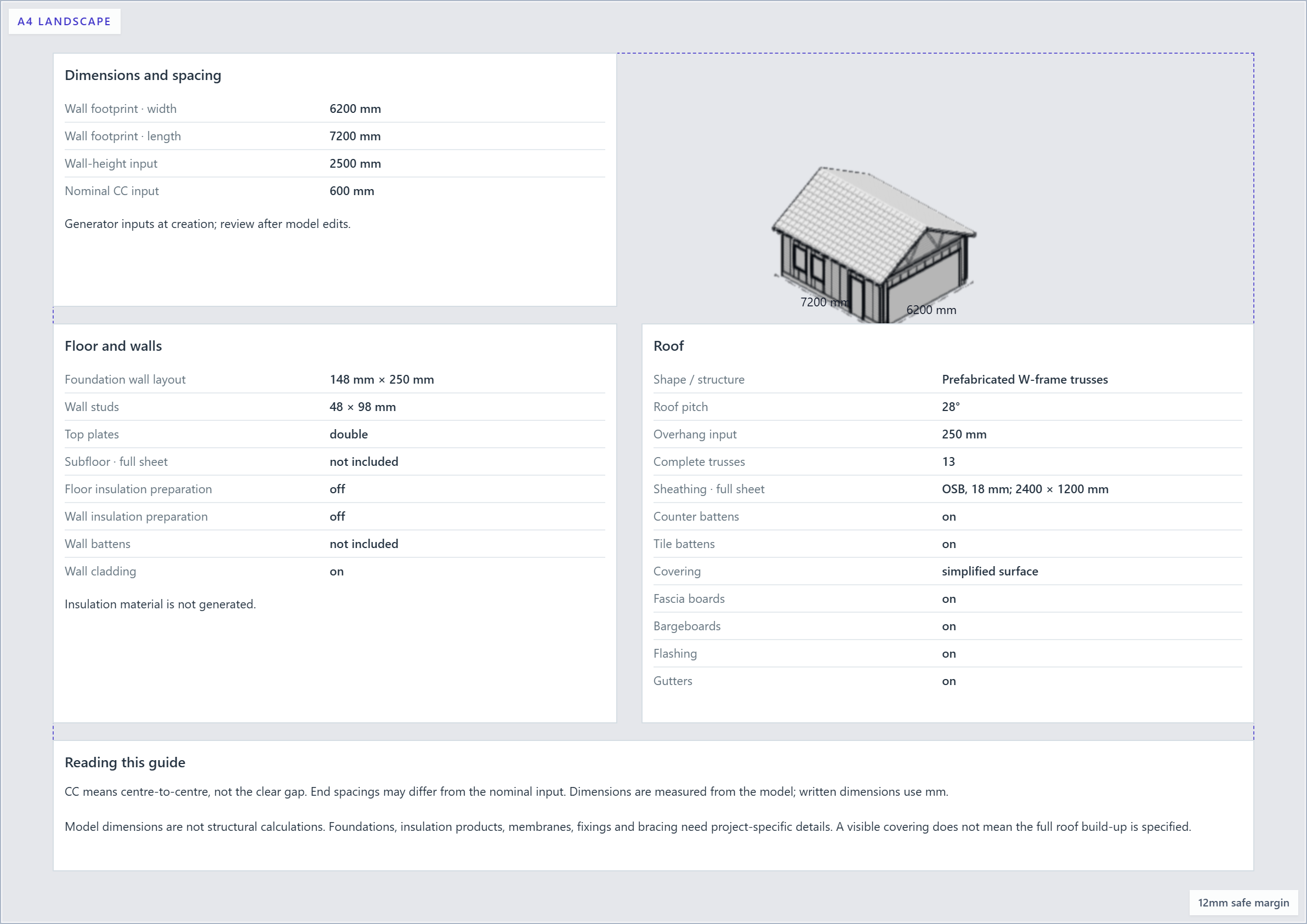
The specification gathers the inputs needed to understand the model: dimensions, wall height, nominal centre spacing, roof form and pitch, member sizes, and supported floor, wall and roof settings. Information about cladding, battens, roof layers and accessories helps the reader see what is included.
Some values describe the generator settings recorded when the building was created. If you have since edited the model, compare those inputs with the actual geometry. Older projects may not have trustworthy creation settings; the guide identifies missing information instead of guessing it.
Centre-to-centre spacing deserves particular attention. A nominal CC setting is not a promise that every gap is identical, and it is not the clear distance between members. The drawings use the model’s actual positions; end gaps can differ from the repeated internal spacing.
Follow the framing and its measurements
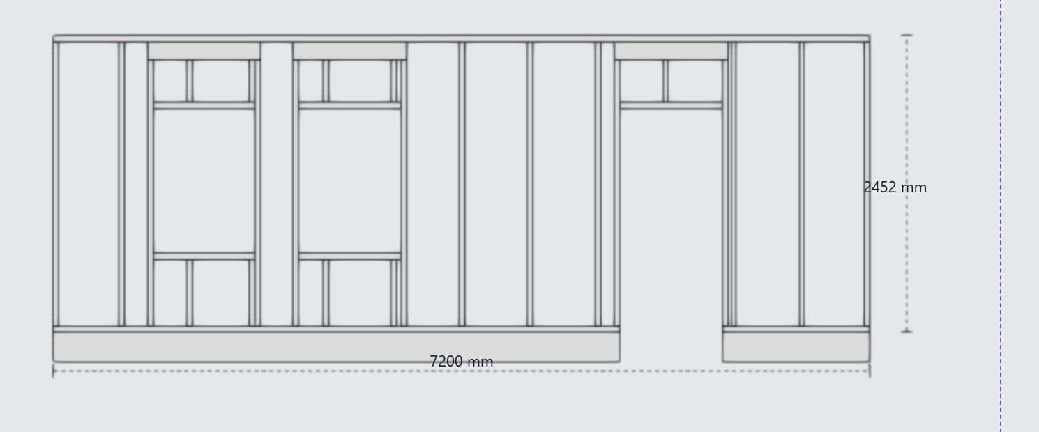
Floor, foundation and wall drawings explain different parts of the building. On supported wall-framing pages, measurements describe the frame shown, including its width, height and stud-centre spacing. A later top-plate stage can add height that is absent from the earlier frame drawing. On densely framed walls, the guide may show representative distinct spacings rather than label every repeated gap; read the note alongside the drawing.
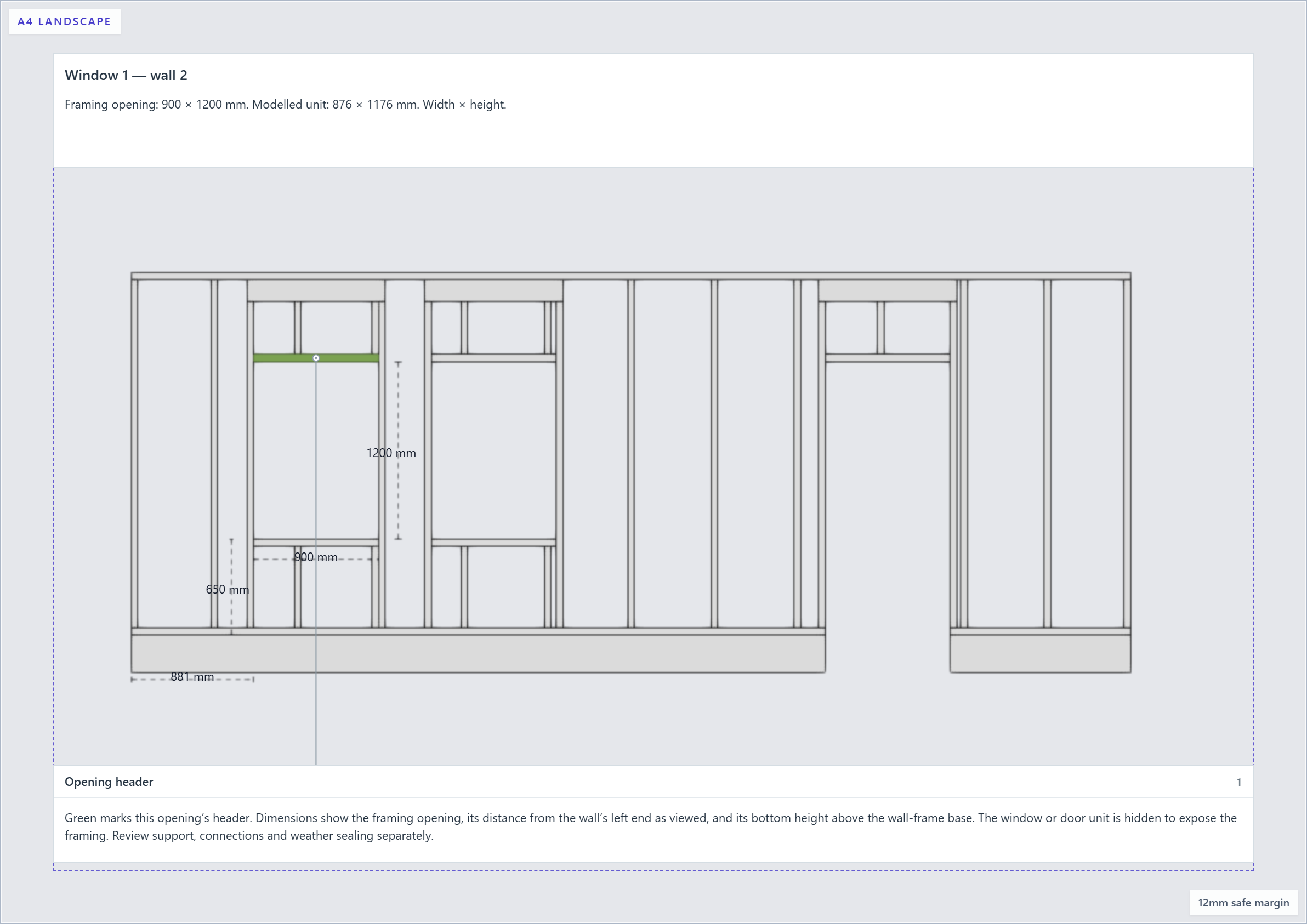
Supported O-framer openings receive larger detail views with opening width and height, their position along the wall, and their lower reference height. The framing opening and the modelled window or door unit have different dimensions. Check which one a drawing describes before using it to order anything.
Garage door openings can also cut the modelled foundation perimeter. Where those cuts are supported and validated, the foundation plan shows the remaining segments and cut-out widths. Door-height dimensions use the relevant lower reference shown by the model. These pages describe the geometry; they do not specify a complete foundation design.
Connect the parts table to the drawing
Generated material notes use plain white tables with Quantity, Name and Dimensions columns. Callout leaders and highlights help connect those rows to the model. The table is a useful way to check what belongs to a stage, but its quantities still need review before they become purchasing or cutting instructions.
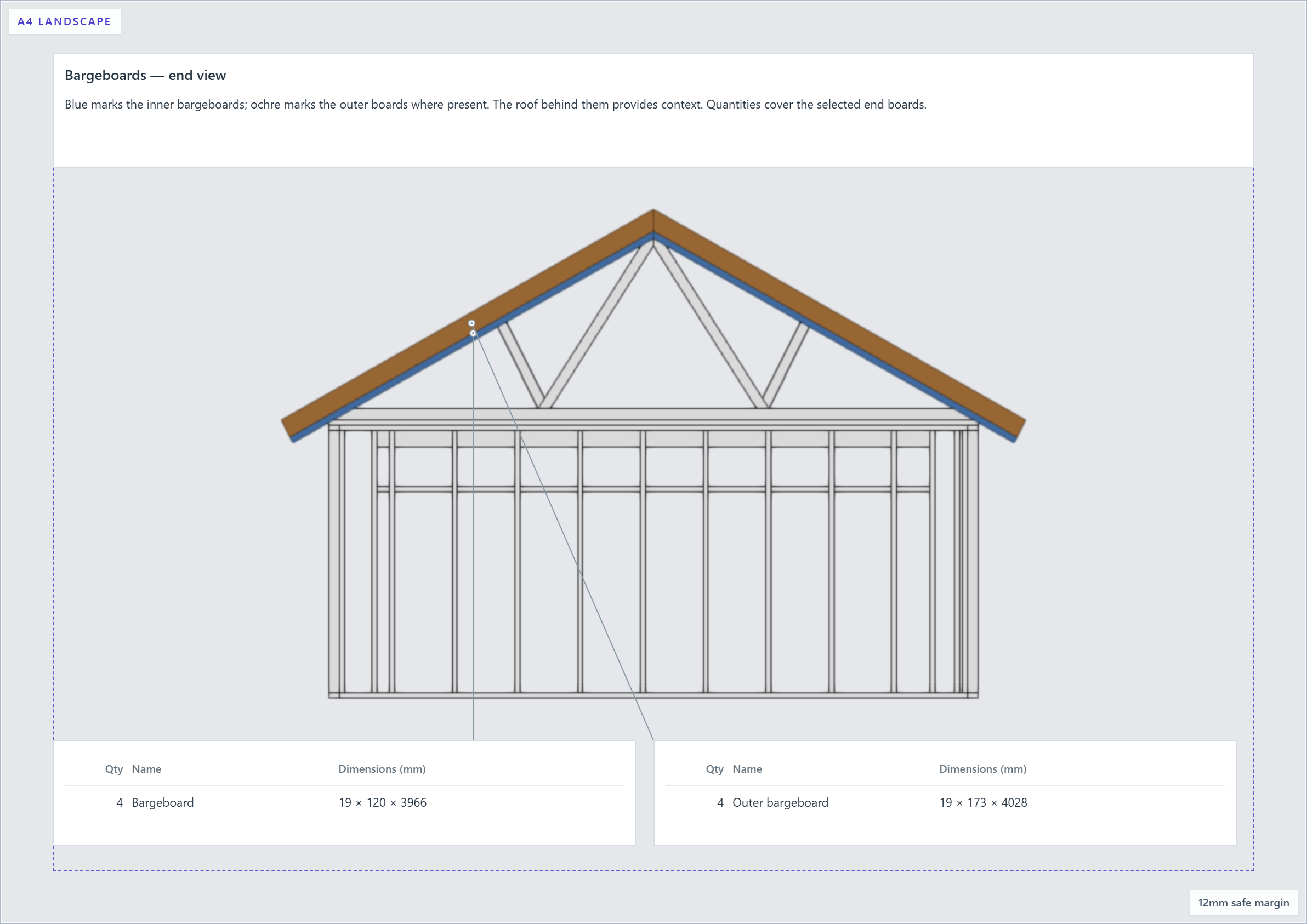
Roof details benefit from context. A set of gutter hooks is easier to understand when you can see where it sits on the fascia. The larger accessory drawings retain reference framing and highlight the relevant hooks, fascia or bargeboards. Some views show one side while the associated note counts both sides; read the scope of the table before comparing it with the visible parts.
Reference parts and repeated detail views are not counted again as new materials. Likewise, a simplified roof surface represents a model component, not a count of individual roof tiles.
Give important details their own substeps
A page becomes difficult to read when a long explanation, a parts table and a measured drawing all compete for space. Substeps let you separate those jobs while keeping them together in the booklet.
For example, a main step might explain the wall framing and list its parts. 9.1 could provide a larger measured view of that wall, while 9.2 could show an opening from another angle. The numbers are managed by Planner; a substep is still a full page in the exported PDF.
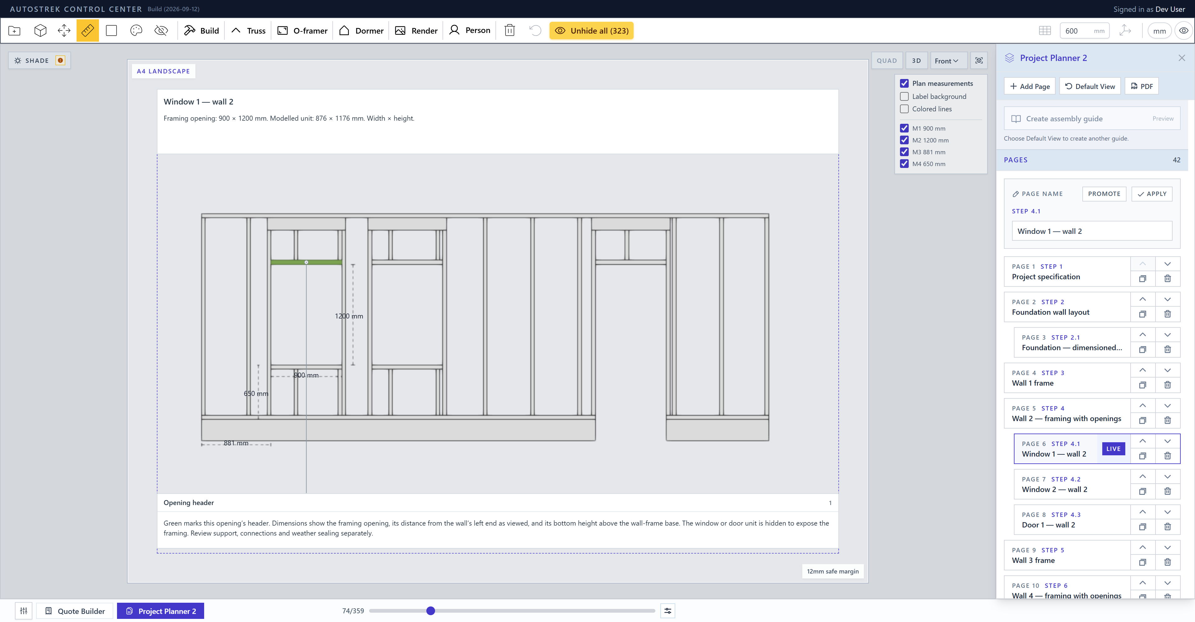
To make your own detail page, select a useful source page and click its Duplicate control. The copy becomes a substep under the same main step and is selected for editing. Give it a descriptive title, adjust its view, and remove or shorten copied notes that are unnecessary on the detail sheet. Switch back to the parent to confirm that it still reads as intended.
Use Promote on a selected substep if it needs to become an independent main step. Add an unrelated drawing with Add Page, which creates a main page from the current view. A manually added page captures that view; it does not automatically inherit a generated stage explanation or parts summary.
Review and edit without losing the structure
The automatic guide creates a draft you can develop using normal Planner controls. A careful editing routine keeps the relationship between the page, its drawing and its explanation clear.
Select the page before changing its presentation
Choose the intended page before adjusting the camera, visibility, notes or measurements. The active page receives supported view changes. If you want to keep the original composition as well, duplicate it first and make sure the copy is selected.
Each page stores presentation information, but all pages refer to the same building model. Changing a member’s geometry, deleting an object or regenerating a building can affect several pages. A duplicate page does not create a separate model revision.
Default View restores the working baseline for the Planner session. Use it to leave a partially hidden or moved presentation view and inspect the building. It does not undo geometry edits or restore deleted objects from your last saved file.
Make the text fit the drawing
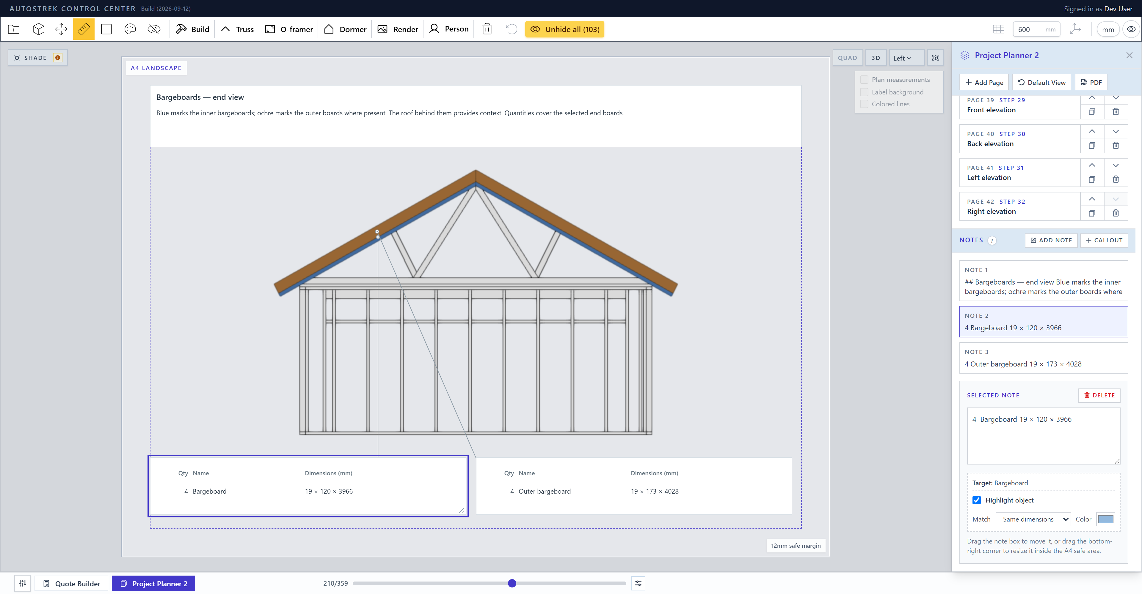
Edit notes and callouts in their normal text field. Keep material names, quantities and dimensions together, and preserve the column structure when editing a table. A generated row such as 9 × Rafter (48 × 98 × 2029 mm) can be edited as text and is presented as quantity, name and dimensions. Changing a number in a note changes the document text; it does not resize a member in the model.
Drag a note to move it and use its lower-right resize handle to make room for the text. Check that long names and dimensions are visible, callout leaders point to the intended part and labels stay inside the sheet’s safe area. A cleaner detail substep is often more useful than shrinking everything to fit one crowded page.
Generated text follows the selected English or Norwegian language when the guide is created. Existing pages keep their text when you change the app language, protecting your edits. For a booklet in another language, create and review a new draft or translate the existing text yourself. Generated dimension text uses millimetres; drawing measurement labels follow the app’s unit setting.
Move, rename and delete deliberately
- Rename by subject. Use titles such as “Front wall — opening framing.” Planner supplies the step numbering, so there is usually no need to type numbers into the title.
- Move a main step as a group. Its linked substeps move with it. Substeps can move within their group. Inspect the reading order after any change.
- Delete only the pages you intend to remove. Deleting a main step keeps its substeps and turns them into independent main steps. If you meant to remove the whole chapter, review and remove those pages too.
- Recheck references after renumbering. Step labels update, but a sentence you typed such as “see step 9” still needs your attention.
Adding a manual page or editing a note does not require you to regenerate the guide. Save a revision before larger changes, and keep your earlier .strek file until the revised booklet has been checked.
When the building changes
Page selections follow the identities of the model parts they contain. Reordering the build animation timeline should therefore preserve those selections. Adding or removing timeline parts is a more substantial change: affected pages can be flagged for review, and PDF export identifies pages that still need attention.
Open each affected page and inspect the actual result. You can select a new stage with the timeline, or choose Reviewed — keep this selection after checking that the remaining selection is still appropriate. That acknowledgement does not repair the drawing or rewrite its text for you.
The review check is about part membership. Moving or resizing an existing member can also make an old measurement, note or callout inappropriate without producing the same warning. After a design change, check the specification, visible parts, dimensions and written instructions yourself.
For substantial geometry changes, save a revision and generate a new guide from Default View. It will be appended to the existing pages. Compare it with your edited version, carry over the information you still need, and remove obsolete pages deliberately. Generated descriptions and quantities on old pages are not automatically rewritten to match a new building.
What is supported today
The feature is experimental and covers recognised generated structures. The standard gable-roof shed and the supported Cabin / Shed, Double Garage, House and Sauna starters have guide rules for their respective framing systems. These include the supported ridge-beam roof, the Garage’s original W-frame trusses, the House’s supported attic-truss and loft arrangement, and the Sauna’s single-slope roof frames.
Supported preparation layers, wall battens, wind-barrier boards, siding and roof accessories can receive their own stages. Prepared for insulation means preparation for it: the insulation material itself is not generated. A visible roof covering likewise does not mean every membrane, fixing or layer of a complete roof has been specified.
Dormers and special openings still need more work
The Dormer tool is not yet supported by automatic assembly-guide generation. You can use the modelling tool in Autostrek, but a model containing a dormer can be blocked by the guide’s current checks. Dormer parts need dedicated rules for their framing, roof junctions, sequence and drawings.
O-framer support is currently for complete, rectangular windows, doors and garage doors in supported generated main walls. Overlapping or sloped openings, special upper-gable or loft hosts, and incomplete framing need further coverage. Other foundation arrangements, truss templates and unrecognised or unsequenced parts can also prevent automatic generation.
The preview explains these cases rather than creating pages with missing parts. Manual Planner pages remain available for views you compose yourself, but adding one does not make an otherwise unsupported model pass the automatic guide checks. Keep the modelling features’ capabilities separate from the automatic document generator’s current coverage.
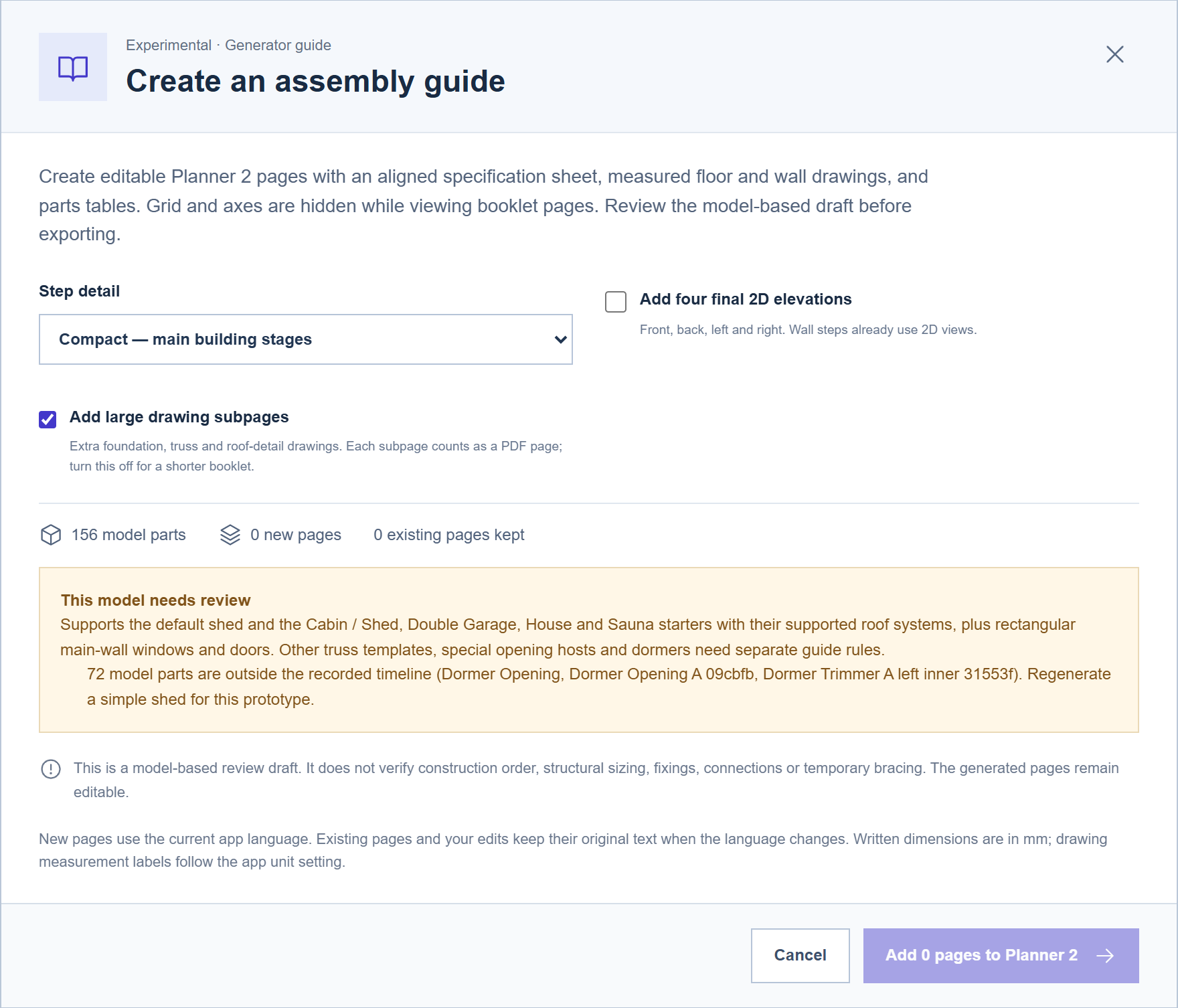
A model-based draft still needs construction knowledge
The guide organises model parts and recognised assembly stages. It does not verify a safe real-world erection sequence, structural capacity, lifting method, temporary bracing, connections, fixings or weatherproofing details.
Saved truss geometry is not a calculation that establishes suitability for every span or local load. Follow the truss supplier’s design and installation information where applicable. Add the foundation, structural and installation details your particular project requires before relying on the booklet as construction documentation.
Export a PDF worth sharing
Before exporting, read through the pages in order. Check the title, visible parts, note layout, measurement reference points and any unfinished review notices. Then open PDF in Project Planner 2.
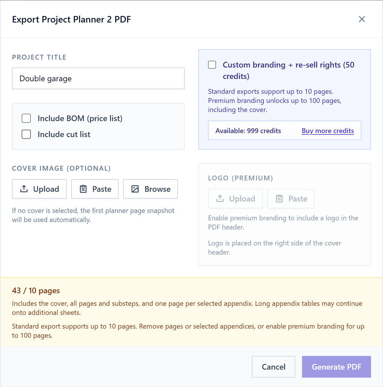
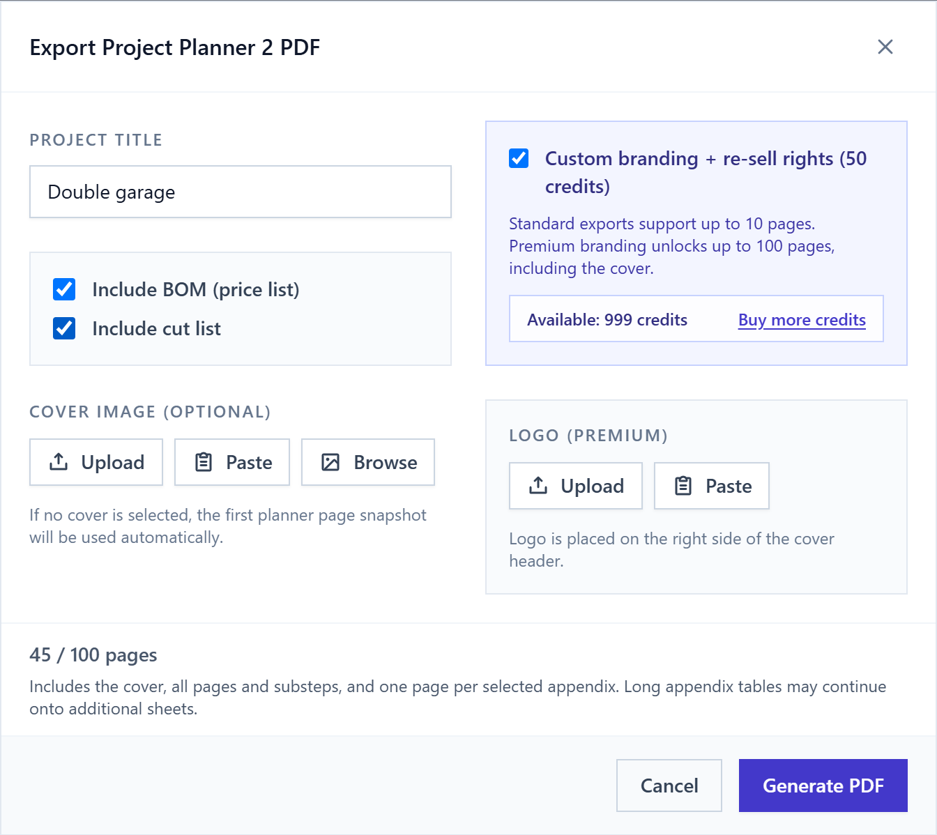
The export window lets you set the project title, choose a cover image, include a BOM (price list) or cut list, and enable premium branding. You can upload or paste a cover image, or browse stored project renders when the project connection is available. If you do not choose a cover image, the exporter uses the first Planner page’s snapshot.
| Option | Standard export | Premium branding |
|---|---|---|
| Page allowance | Up to 10 | Up to 100 |
| Export credits | No premium-export credit charge | 50 credits per export |
| Project title and cover | Included | Included |
| BOM and cut-list appendices | Optional, within the limit | Optional, within the limit |
| Custom logo | Premium option | Optional; placed in the cover header |
| Branding / re-sell option | Standard presentation | Premium export option |
The count includes the cover, every main page, every substep and one entry for each selected appendix. Nine Planner pages plus the cover reach the standard ten-page allowance. A selected BOM or cut list adds to that count; long appendix tables can continue onto additional physical sheets.
Generate PDF is disabled when the count exceeds the selected limit. Remove unnecessary pages or appendices, or enable premium branding if the larger allowance suits the booklet. The dialog shows the available credit balance and a top-up link. Review material quantities, units and supplier prices before including the BOM or cut list.
Clear text and clean illustrations
Notes, parts-table text, callout leaders and measurement labels now export as selectable vector text and lines. They remain sharp when zoomed or printed, while the model drawings remain images. Re-export an existing booklet to get the improved text; an already downloaded PDF will not change. Text embedded in an imported image is still part of that image.
Partial 2D assembly illustrations omit the extra ground line, keeping the focus on the parts and their measurements. Complete building elevations retain it, as do quad view and elevation exports. Grid and axes are omitted from Planner PDF captures; intentional measurement lines remain.
Let each page finish preparing
The exporter works through the pages, restores their views and selected parts, captures the drawings and prepares the PDF. Bigger booklets take longer. During capture, each page has up to one minute of active-tab time to become ready; switching to another browser tab pauses that readiness timeout.
If a page cannot be prepared, the message identifies its number and title and what could not be restored. Return to that page, inspect its view and selection, and retry after resolving the problem. A review warning should be addressed before exporting rather than worked around by hiding the affected parts.
Save the editable .strek project as well as the PDF. Return to Default View and inspect the full model before saving, then reopen the file to check the booklet. Current saves use .strek version 3; older installed Viewer versions can require a compatible update or a GLB geometry export. The PDF is the shareable document, while .strek retains the editable project.
An example booklet
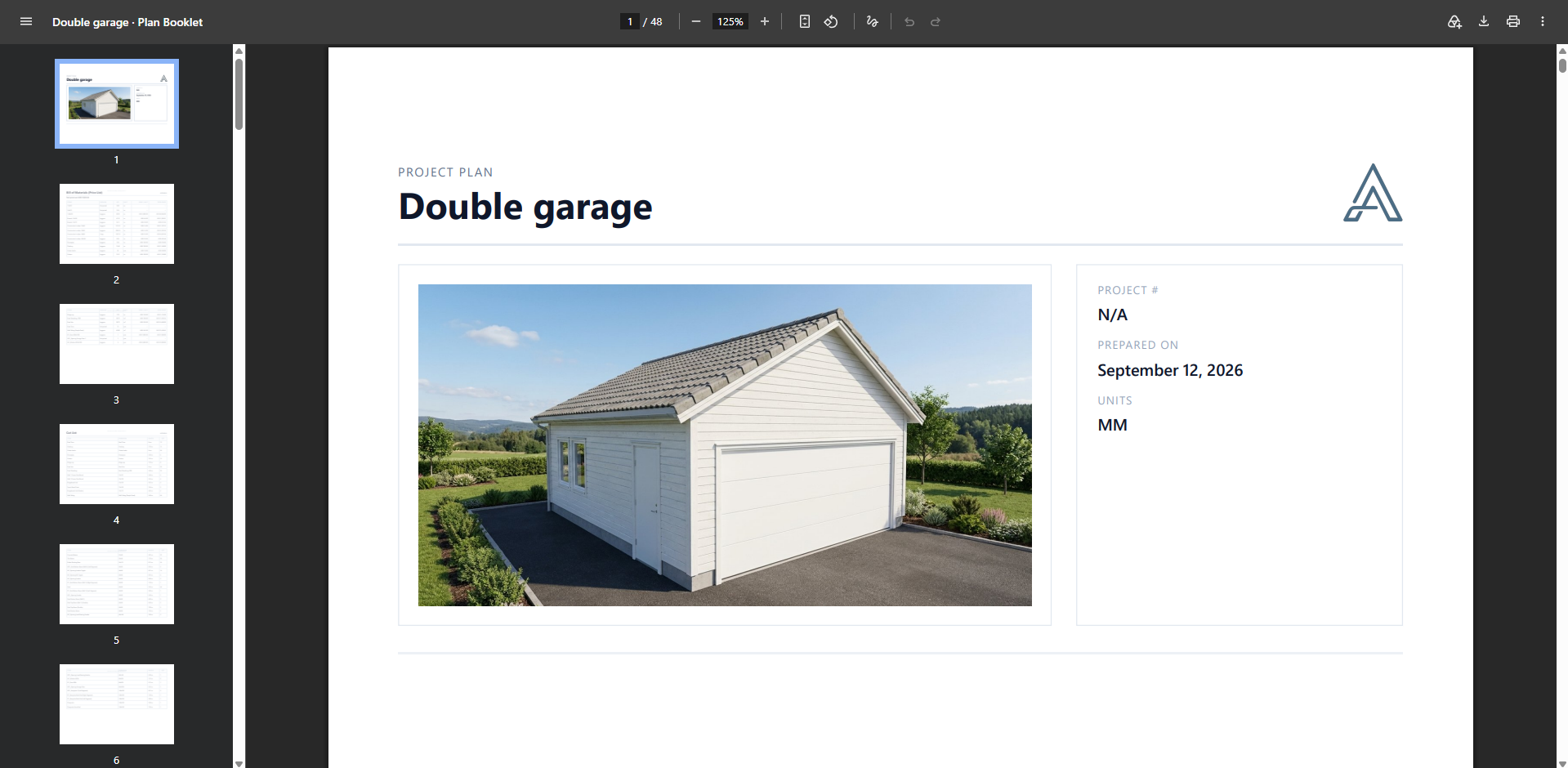
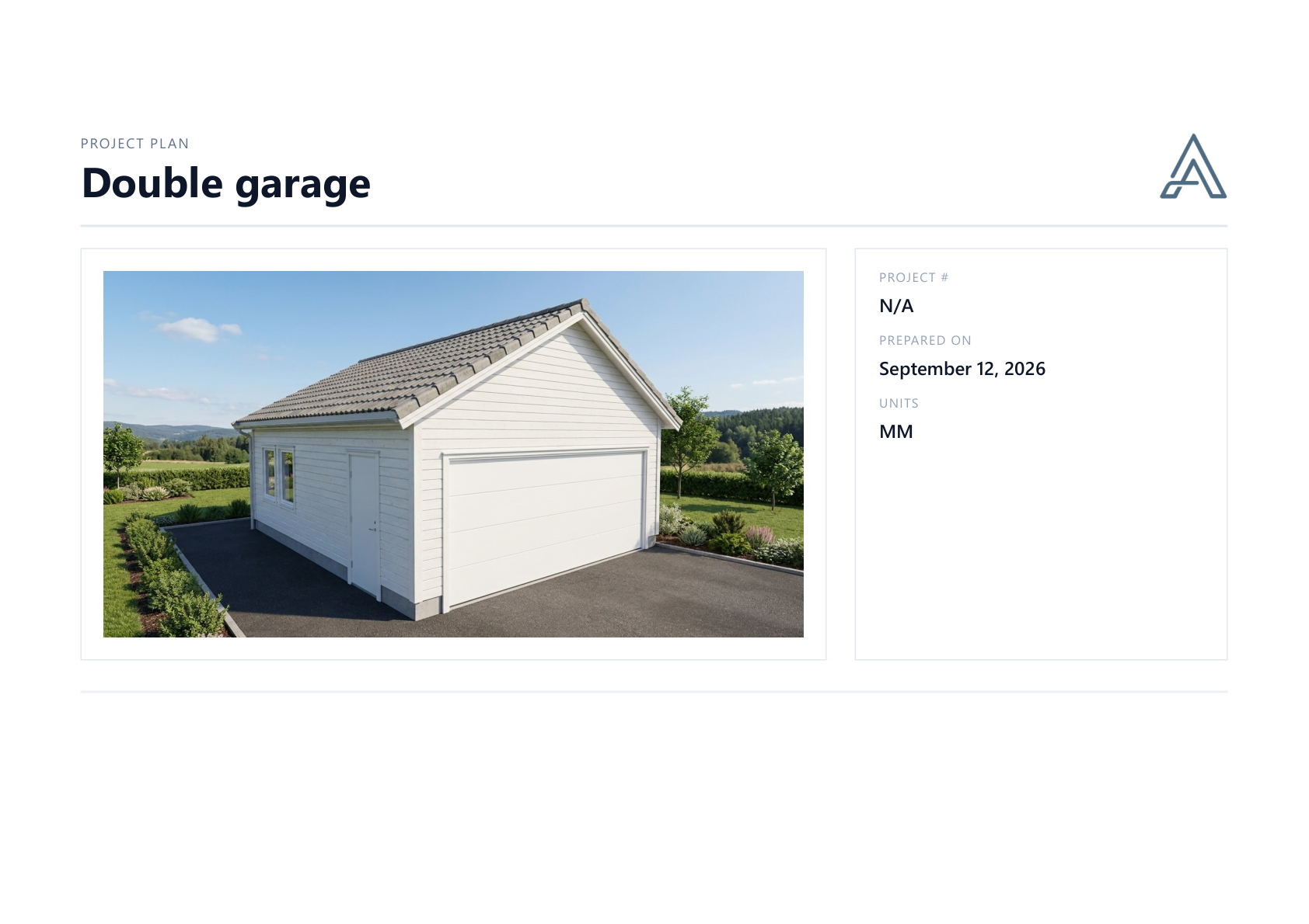
Explore the Double Garage booklet to see the page layouts, drawing scale and how the main steps relate to their details. Its 42 planner pages, cover and five BOM/cut-list sheets make 48 PDF pages in total. Use it as a layout reference when reviewing your own booklet.
 Open the booklet
Double Garage booklet
Straight from the generator. This example was exported to PDF without any manual edits to the automatically generated pages.
Follow the specification, framing, opening details and roof accessories through to the four final elevations. The file also includes the bill of materials and cut list.
Exported September 12, 2026. Dimensions, quantities and prices relate to this example project.
A sensible first project
Begin with a saved copy of a simple supported building. Generate a Compact draft, keep the larger drawing substeps, and inspect the specification and one wall chapter closely. Duplicate a page, turn it into a useful detail, and adjust a note so it reads well at the final paper size.
Save and reopen the project before preparing a short PDF. Once that workflow feels familiar, work through a larger Garage, Cabin, House or Sauna booklet and add the explanations your project needs.
The automatic guide takes care of much of the initial page preparation. Your review turns those pages into a document someone else can understand.
For the detailed reference, see the assembly-guide knowledge base, the Norwegian guide, Planner page state and PDF export options.