A window’s position matters from both sides of the wall. Outside, it helps define the elevation. Inside, it determines where you can put a partition, a kitchen counter or a bed. Being able to work on those decisions together makes a building easier to plan.
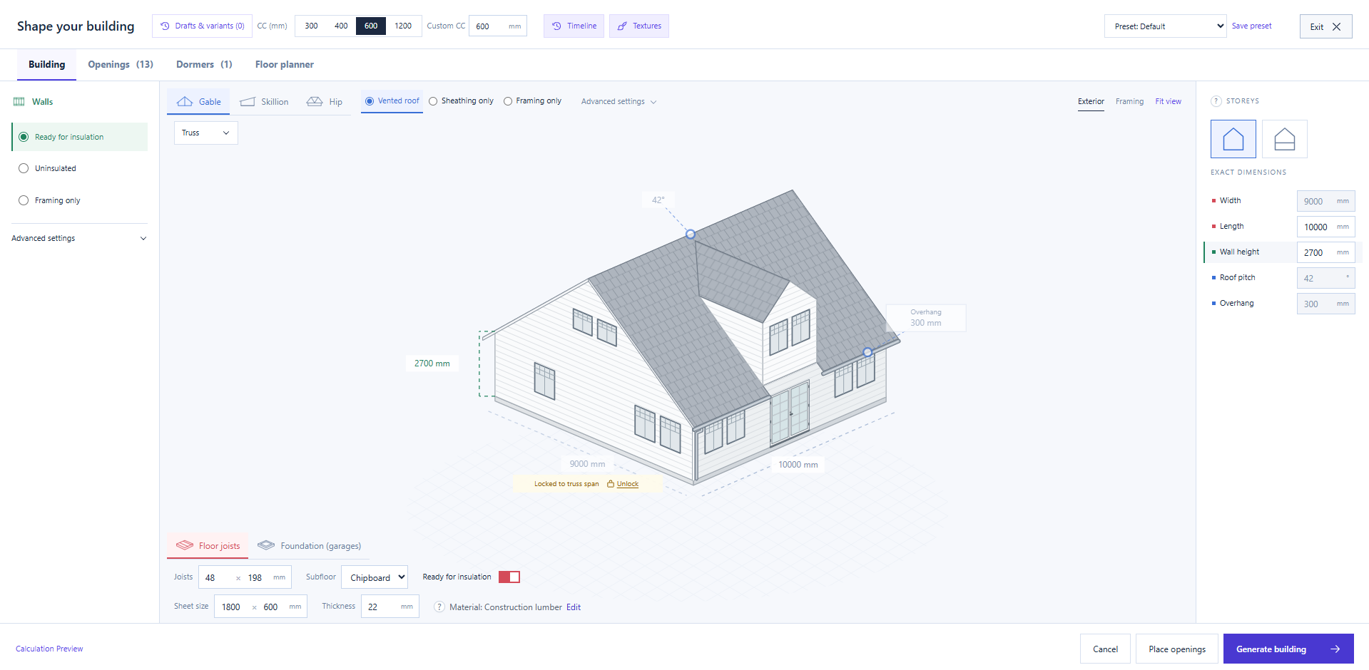
The new Visual Build Generator brings the exterior, openings, dormers and room layout into one workspace. You can develop the design in a responsive preview, check how its parts fit together, and generate the 3D building when you are ready.
Buildings can now have two full storeys, with a third level in the loft when using compatible attic/A-frame trusses and a loft deck. That opens up more possibilities for houses and cabins while keeping the floors, walls and roof in the same design.
The latest addition is Floor planner: a top-down view for internal walls, doors, room dimensions and furniture. It shares the building dimensions and exterior openings with the other views, so a change made in one place carries through to the others.
One design, four views
Open Build to enter the visual designer. Four modes give you different ways to work on the same building:
| Mode | What you can work on |
|---|---|
| Building | Overall size, storeys, floor system, wall construction, roof and finishes. |
| Openings | Windows, doors and glazed facades, with precise sizes and positions. |
| Dormers | Supported dormers and building extensions, seen in elevation, roof plan or 3D. |
| Floor planner | Internal walls, doors, room labels and furniture, alongside the existing exterior openings. |
Move between the views as the design develops. For a small cabin, you might set the overall size, place the main windows, then draw a bedroom partition and move a window to suit that room.
Start with the building
Set the width, length and wall height, then choose the floor, wall and roof construction. The preview gives you an immediate view of the proportions while the surrounding controls keep dimensions and material choices close at hand.
Start from a blank design or choose Customize on a startup building such as the cabin, garage, house or sauna. These examples bring their saved openings and roof settings with them, giving you a useful starting point to adapt.
Choose a supported roof structure or saved truss, then adjust the finishes while keeping the underlying construction in view.
Plan one, two or three levels
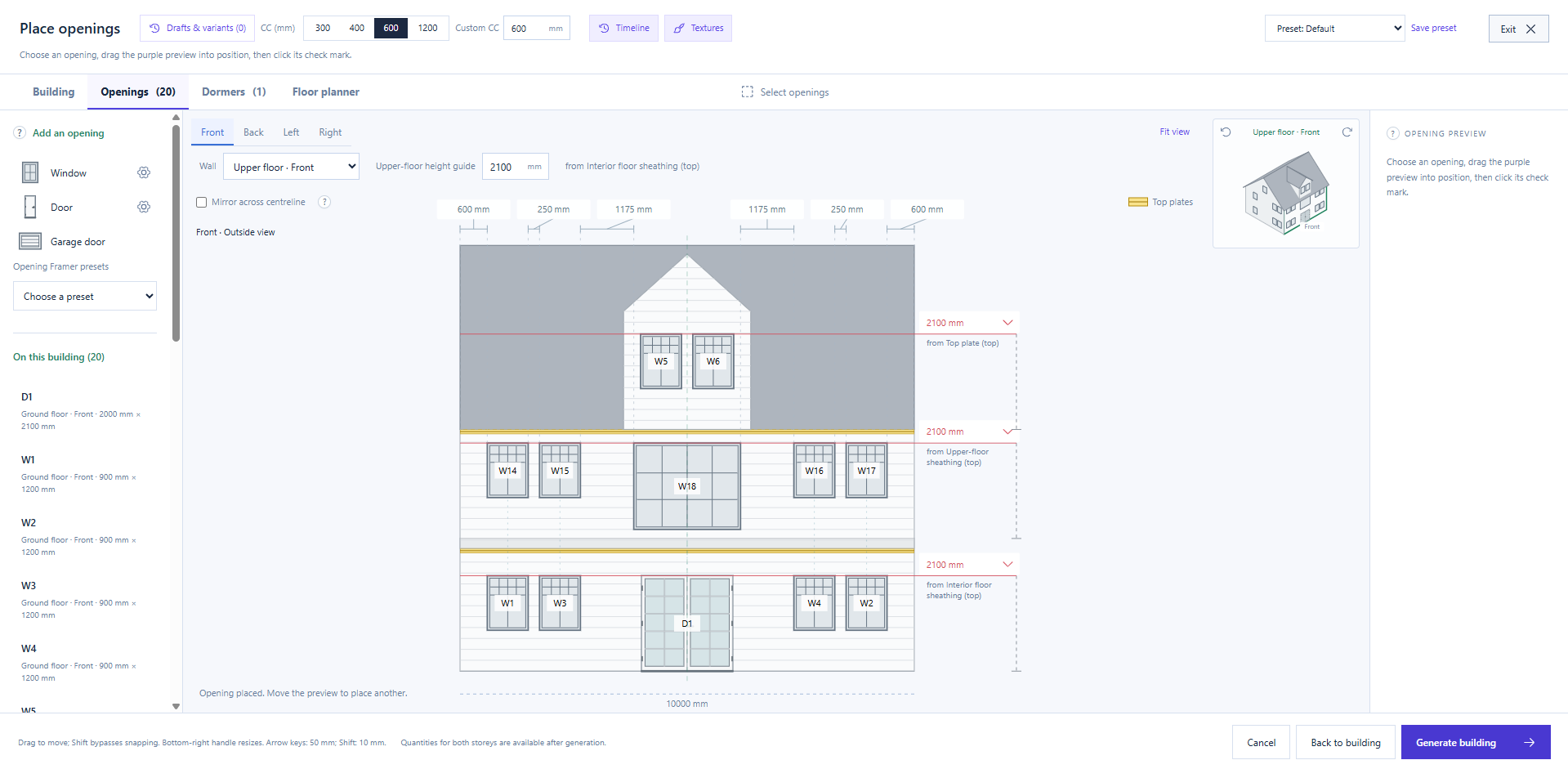
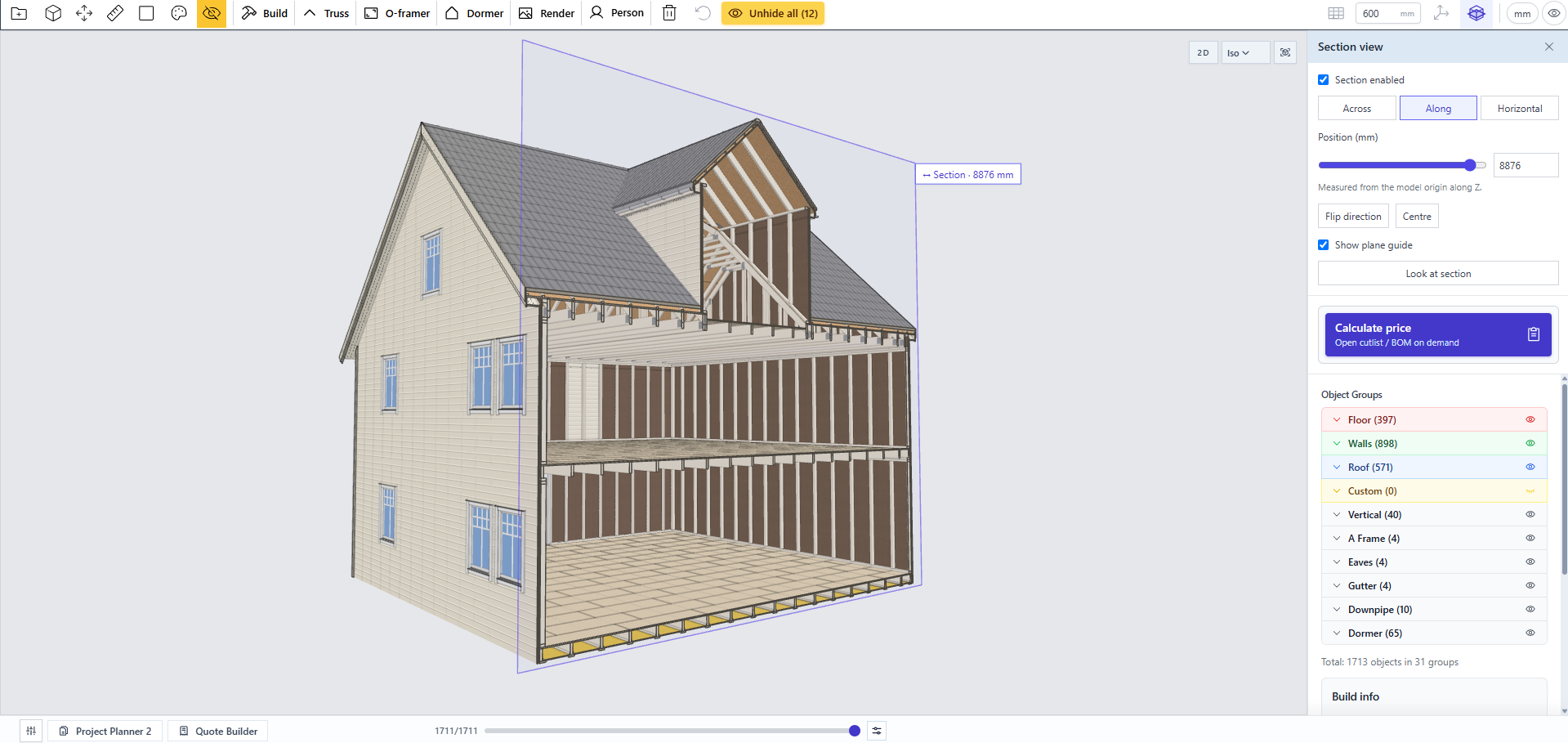
The new Storeys control in Building lets you choose one or two storeys. With two selected, set Wall height 1 and Wall height 2 separately. The upper floor and roof follow changes to the lower walls, helping you explore proportions while keeping the levels connected.
Under Upper-floor joists, set the intermediate floor’s joist dimensions, CC spacing and deck thickness. Both storeys share the building footprint, with their own opening positions and wall heights. You can also give the upper storey a different siding finish and add a separator board between floors.
Add a compatible saved attic/A-frame truss with a loft deck and the roof space becomes a third planning level: Floor 1, Floor 2 and Loft. The loft’s usable space follows the truss posts, sloping roof and available headroom. In Floor planner, switch between levels to arrange their internal walls, doors and furniture independently.
For example, a cabin can have living space on the ground floor, bedrooms upstairs and an additional loft beneath the A-frame roof. The same designer handles the exterior and each floor’s layout. See the two-storey building guide for floor settings and height references.
Put windows and doors in context
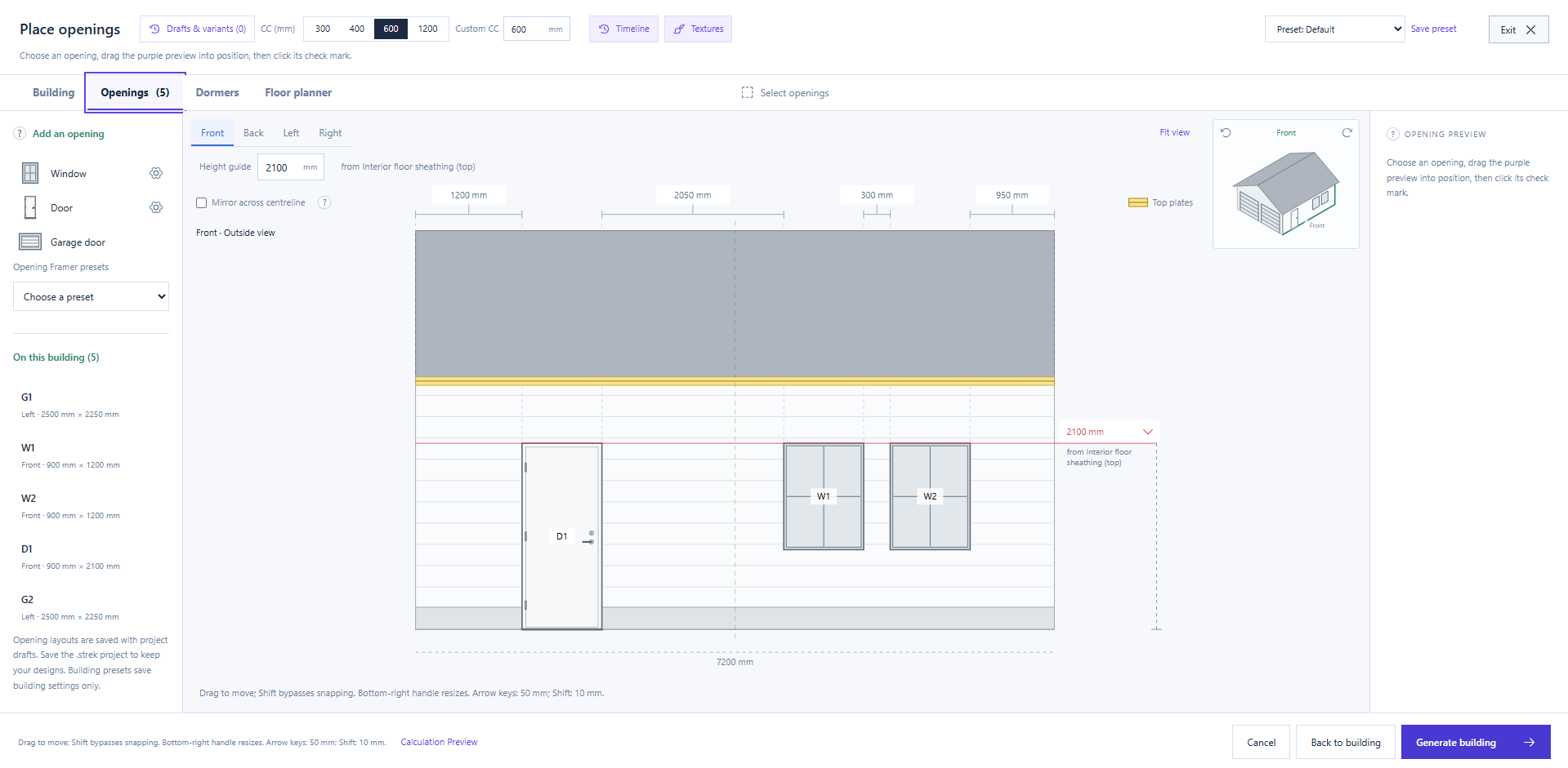
In Openings, place windows and doors directly on the selected wall elevation. Drag the preview into position, then use exact dimensions and gap measurements to set the spacing. The small building navigator helps you keep track of which wall you are editing.
The expanded window and door libraries give you more control over the building’s character. Choose plain window glazing or a grille pattern, then adjust the bars and opening dimensions. Roof-following tops and multi-pane glazed facades add larger areas of glass, with options for bay layout, frame colour and profile sizes.
The door gallery includes plain and glazed exterior styles, single and double balcony doors, and sliding patio doors. The new single balcony door has one uninterrupted glass pane in a slim frame. Set the dimensions, handle side and hinge count for hinged doors; the chosen sizes and styles carry through to the generated model.
Bring dormers into the design
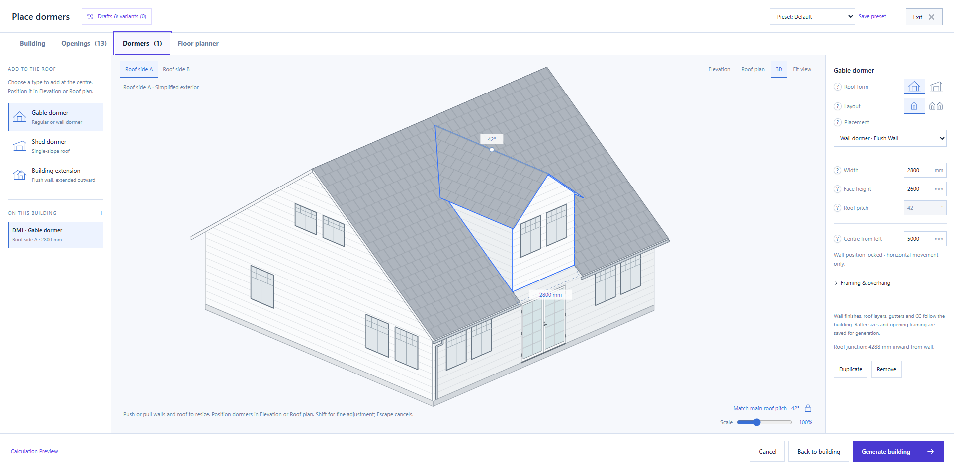
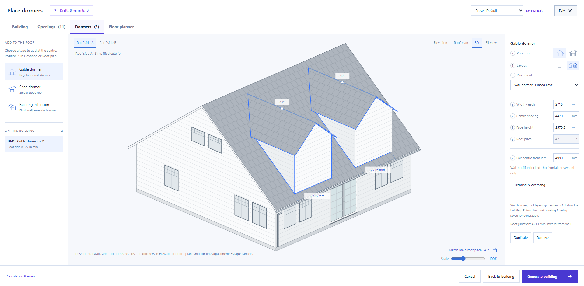
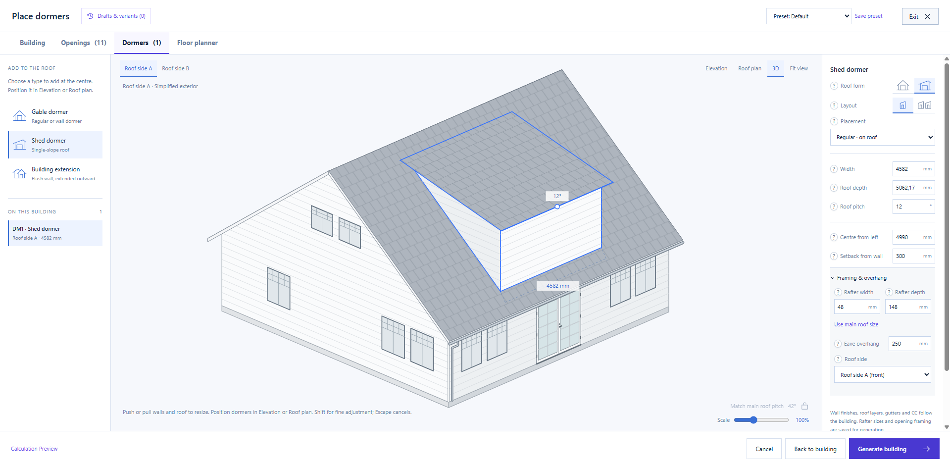
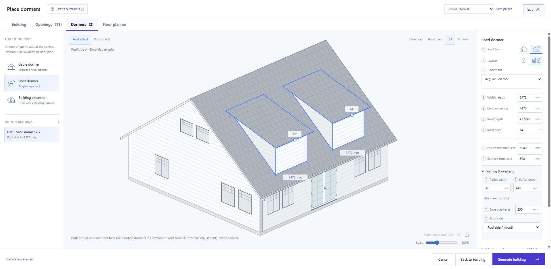
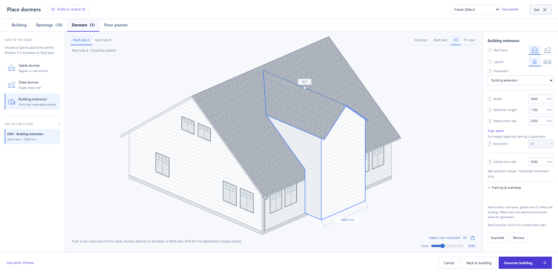
Switch to Dormers to work on a compatible gable-roof building. Choose a gable or shed roof form, with a single dormer or a paired layout. Elevation, roof-plan and 3D views help you judge the width, height and position from different directions. Supported gable configurations can also project outward as a building extension.
Dormers and their openings remain part of the saved design. You can review how the addition meets the main building before generating its framing and roof junctions. The tool identifies fit problems that need attention; available configurations depend on the selected roof and truss.
Plan the rooms inside
Floor planner turns the building into a measured plan. Click to draw connected horizontal and vertical internal walls, use the green snap markers to join corners or meet another wall, and press Enter to finish a drawing chain. Exact lengths and wall positions are available in the inspector.
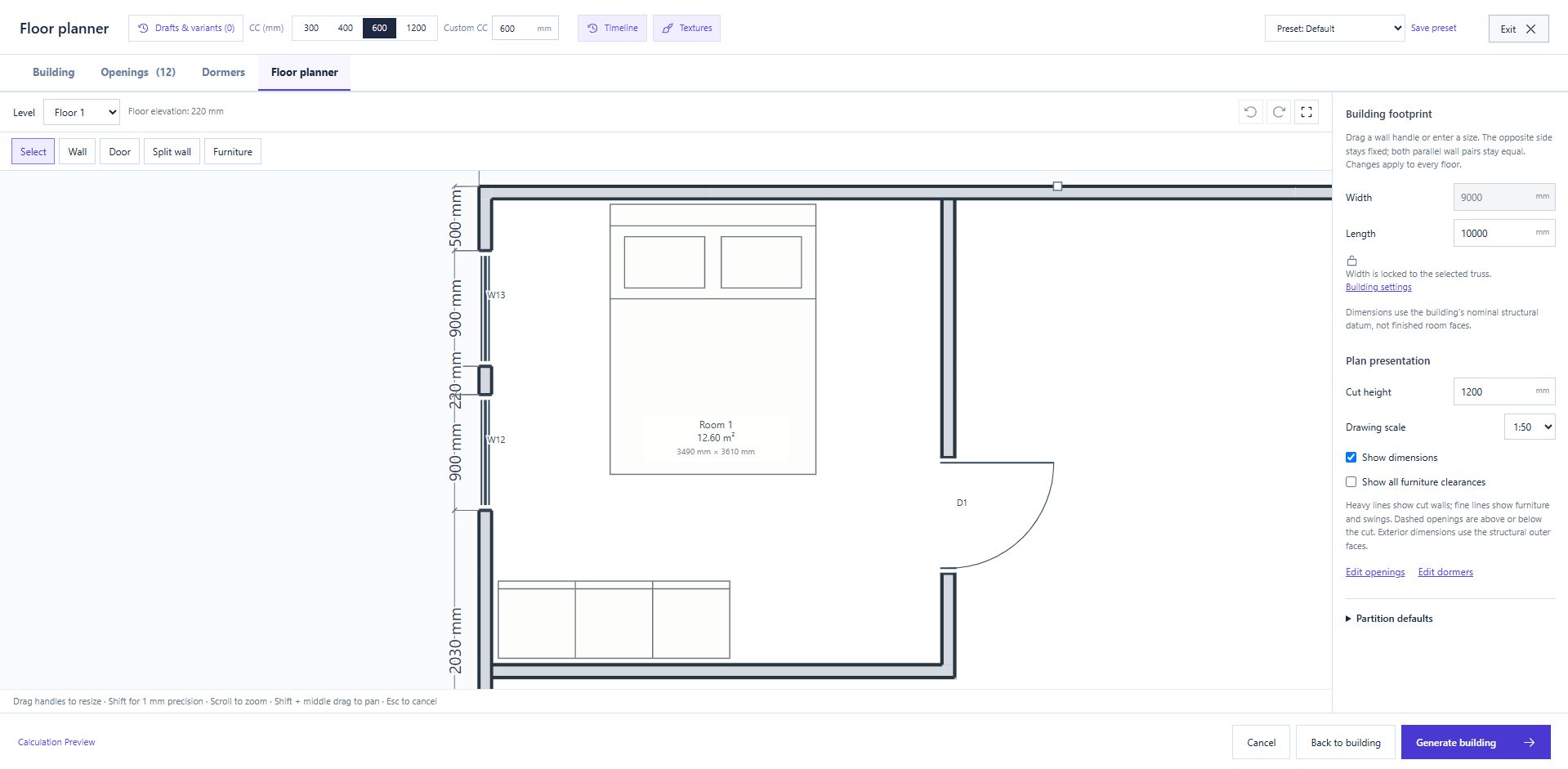
Place internal doors on their walls and choose the hinge and opening direction. Door leaves and swing arcs help you see whether a doorway works beside a corner or an adjoining room. Enclosed rooms receive area and dimension labels, and you can give each room a name.
Existing exterior windows and doors appear in the plan too. Move a window sideways to suit the room and its position also updates in Openings. Drag an exterior wall handle to change the building width or length; the main footprint stays rectangular, and the shared dimensions update across the designer.
Choose Floor 1, Floor 2 when enabled, or Loft with a compatible saved attic/A-frame truss and deck. Loft guides show the posts and areas of low headroom so partitions can fit within the available space.
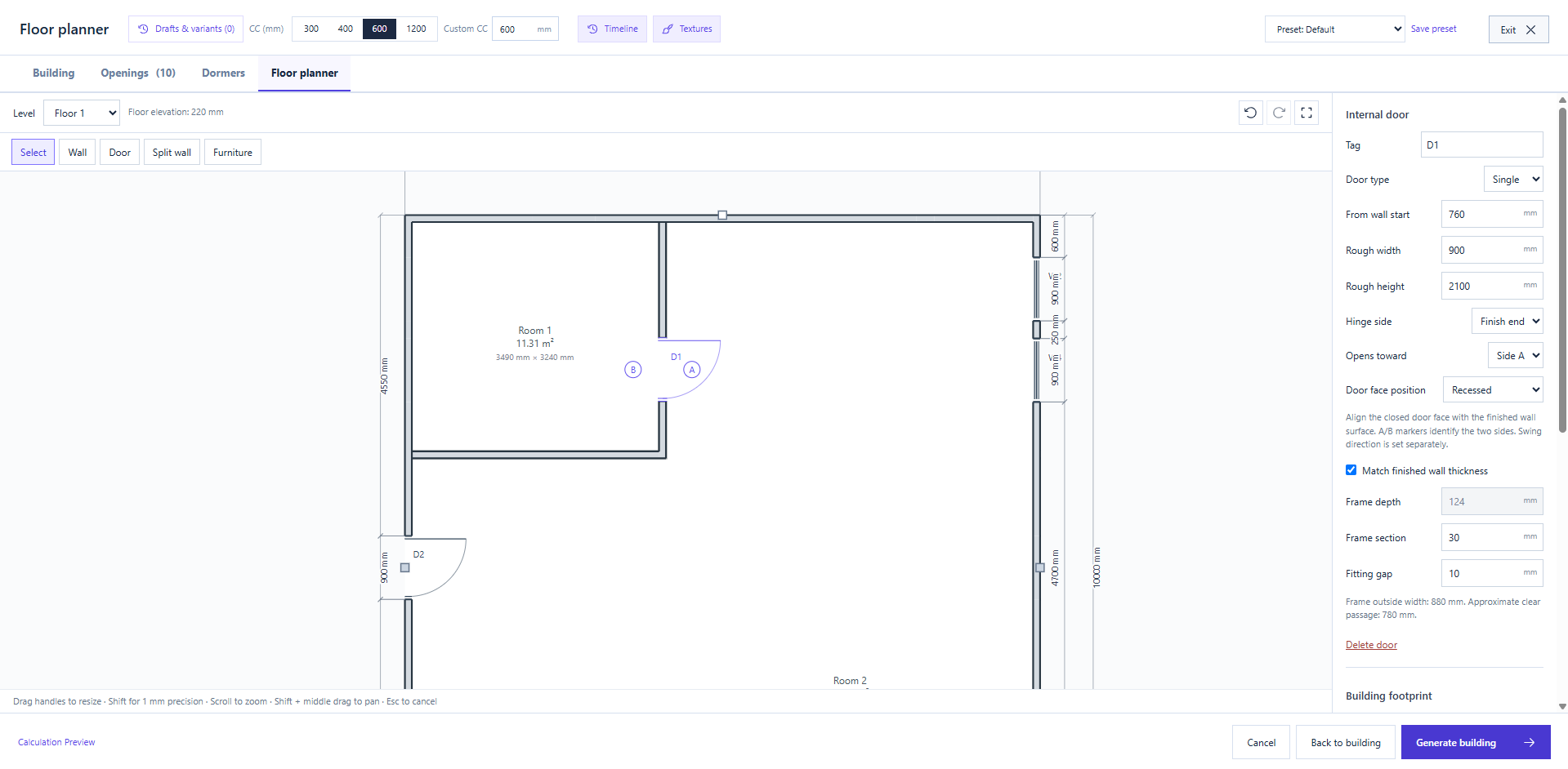
The plan also carries construction choices. Set the stud width and depth and the finish thickness on each side of an internal wall. Partitions follow the building’s CC spacing, with extra studs where needed to keep the final solid bay within that spacing. Walls sharing a type share its settings; Separate wall type lets you change one wall independently.
Make room for everyday life
The Furniture and interior gallery adds familiar top-view symbols for living, dining, sleeping, kitchen, bathroom and storage areas. Place a bed to judge the bedroom, add a table to test the dining space, or arrange kitchen units along a wall.
Move, rotate, mirror and duplicate items. Adjustable symbols have width and depth controls, and optional clearance outlines help you compare the arrangement with nearby walls and door swings.
Furniture and interior items currently appear only in the floor plan. They are saved with the design, but are not included in the generated 3D model. 3D support is in development. The gallery includes a yellow notice explaining this while you choose items.
Turn the layout into a model
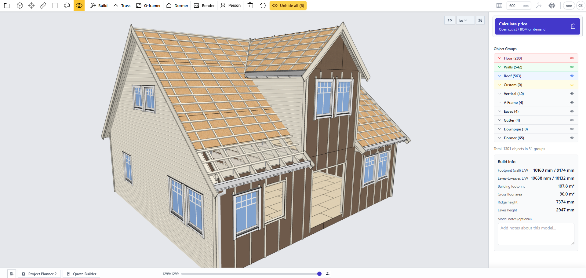
Choose Generate building to review the design, resolve any highlighted issues, then select Build now. Autostrek creates the building with its configured framing and finishes, exterior openings, supported dormers and internal partitions.
Internal walls generate framing, finish panels and hosted doors. The doors have white leaves and frames, with two hinges per hinged leaf. You can set the closed door face flush with either finished wall side and let the frame depth follow the wall thickness. These choices carry from the plan into the model.
Hide selected roof or wall groups to inspect the interior, check the partition corners and compare the generated rooms with the plan. The resulting model remains available for the usual inspection, measurement, cutlist and drawing workflows.
The current floor planner supports orthogonal, non-load-bearing partitions. It does not generate stairs, and its drawing-scale controls do not yet include a dedicated floor-plan PDF export. Use the existing Project Planner for drawing sheets from the generated model. Structural sizing remains a separate project decision.
Keep the alternatives worth exploring
Use Drafts & variants to keep different layouts within the same project. Save a compact version, then try a wider building or a different bedroom arrangement. Each design retains its building settings, placed openings, dormers and floor layout, including the furniture symbols.
Save the .strek project to keep those designs after closing the workspace. Save project copy is also available in the designer before the first model is generated.
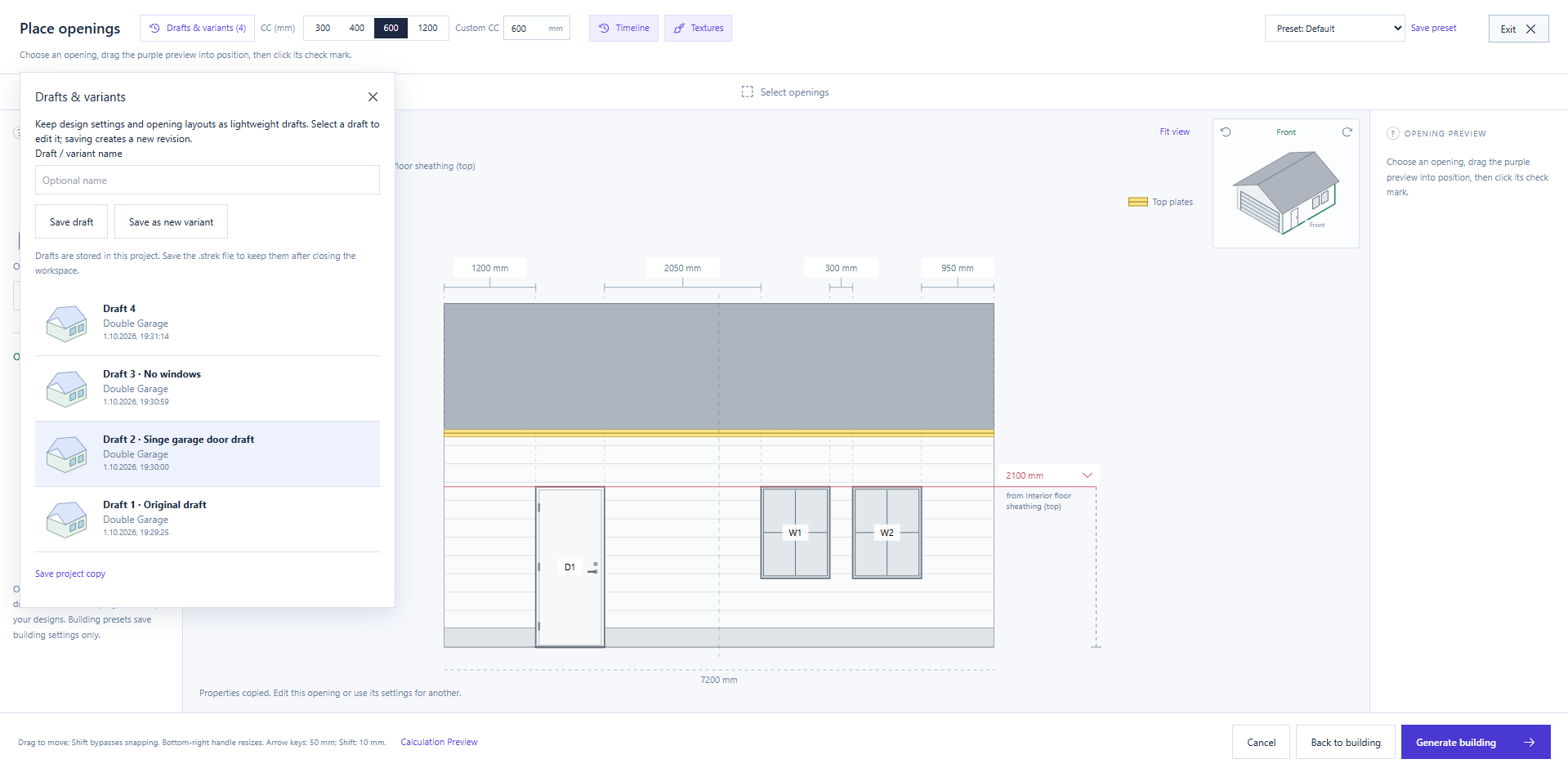
Reopening Build restores the saved design for further changes. Regeneration replaces the current model, including direct 3D edits that were not made in the designer. Save a project copy first when you want to retain that earlier model.
Try it with your next building
Open Build, or choose Customize on a startup design. Set the main dimensions, place a few openings and switch to Floor planner. Draw one room, add its door and place a piece of furniture. Move a window to suit the layout, then return to Openings to see the same change in elevation.
For the detailed controls, start with the Visual Build Generator guide, then explore Floor planner, internal walls and doors and furniture placement.
A few ideas to build on
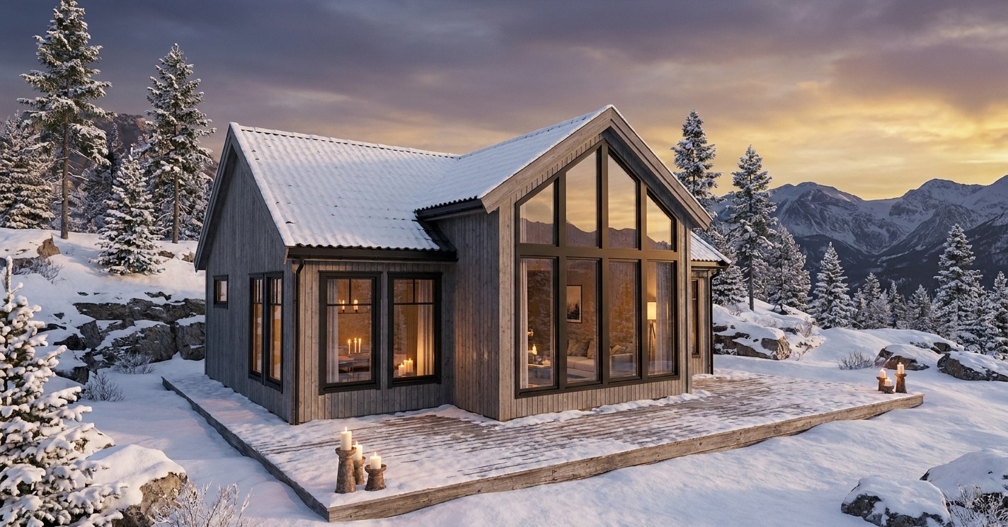
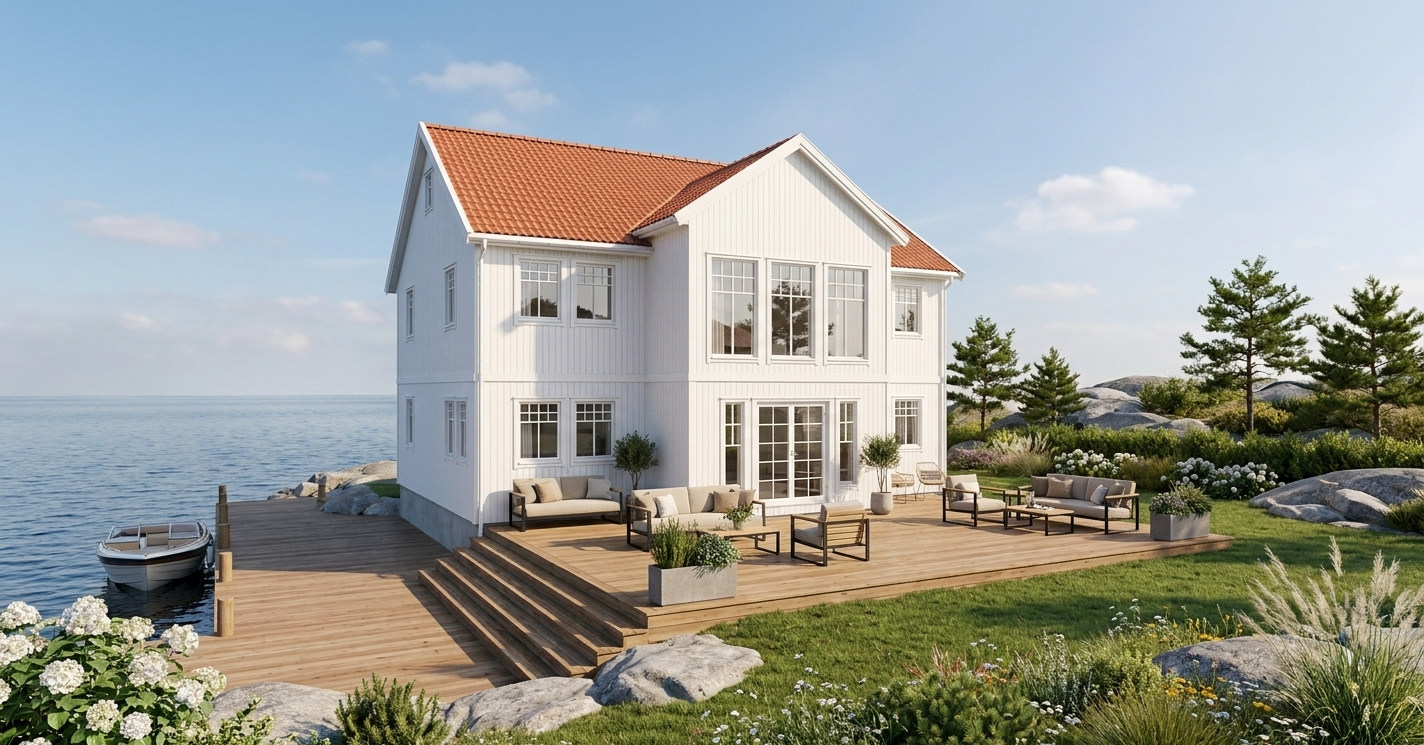
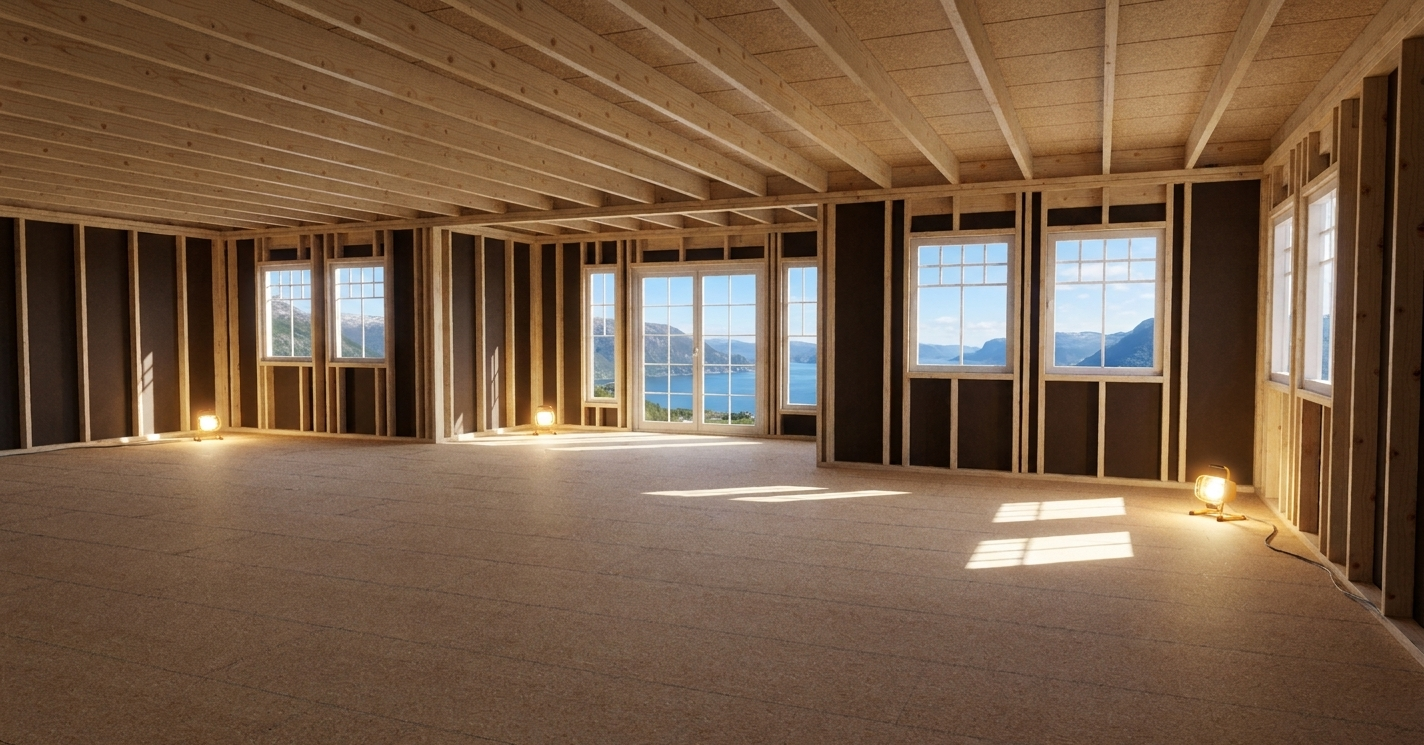
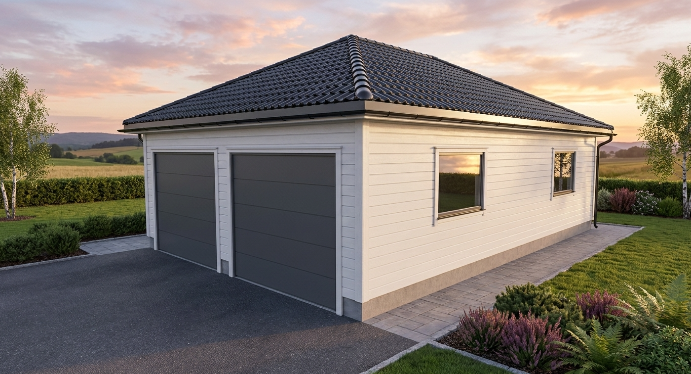
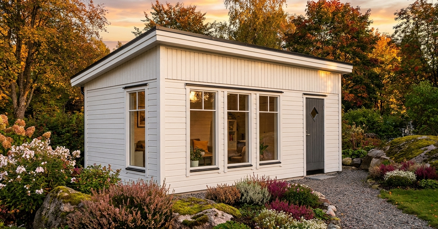
From a mountain cabin with a glazed gable to a two-storey coastal house, these rendered examples show different ways to bring the design together. Explore window proportions, door styles and roof forms, or look inside an exposed timber interior. Materials, lighting and surroundings help present the design in context.
See more project ideas in the Showcase gallery.