Recommended test
Cut through a generated building, inspect its framing, then restore the complete model.
- Open a building and click Section view beside Axes in the main toolbar.
- Choose Across and move the slider until the cut reveals the wall and roof framing.
- Try Flip direction, then Look at section for a straight orthographic view.
- Hide the plane guide and orbit the model to inspect the exposed connections.
- Close the controls with X and confirm the section stays active; click the highlighted toolbar button to restore the complete building.
Look inside the building
Section view creates a temporary section, or snitt, through the building. It hides the geometry on one side of a plane so you can inspect wall layers, floor framing, trusses and roof connections. Members crossed by the plane show filled cut faces with outlines; cavities remain open.
The cut changes the display. Member lengths, original geometry and material quantities stay intact.
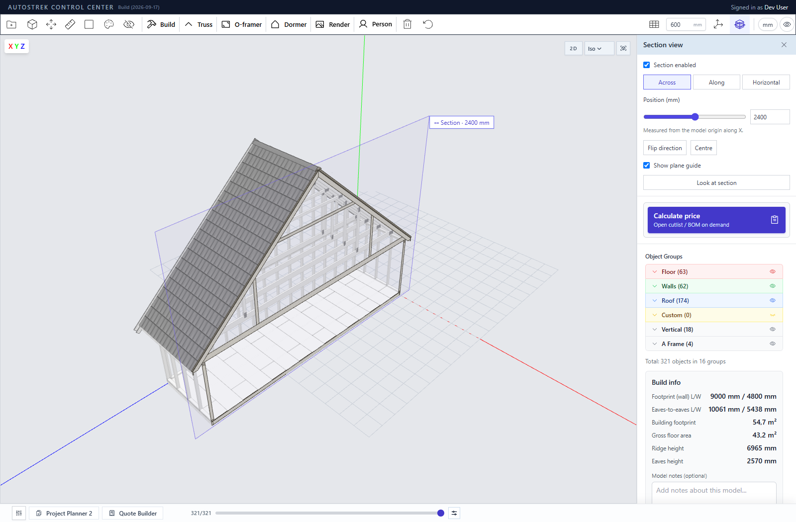
Open and position a section
Click the Section view button, shown as a cube with a plane through it, beside Axes in the main toolbar. The controls open above the right sidebar.
Choose an orientation:
- Across moves a vertical cross-section along the model’s X axis.
- Along moves a vertical longitudinal section along the Z axis.
- Horizontal moves the cut up or down along the Y axis.
Use the slider to explore the model, or enter an exact Position (mm). For a horizontal cut, the field is called Height (mm). Press Enter or leave the field to apply the value. Positions are measured from the model origin along the selected axis, rather than from the nearest wall or floor.
You can also drag the Section handle in the viewport. When the handle has keyboard focus, use the arrow keys for 10 mm steps, or hold Shift for 100 mm steps. Centre returns the cut to the middle of the model along that axis.
Inspect both sides
Use Flip direction to reveal the other half of the building. Choose Look at section to face the cut in an orthographic view, or orbit, pan and zoom with the normal camera controls to inspect it in 3D. Parts beyond the cut remain hidden as the camera rotates.
Clear Show plane guide to hide the guide and handle while retaining the cut. Selection and Tape Measure snapping follow the visible geometry and the cut contours. The same active section also appears in Quad View. Look at section returns to a single aligned view.
Turn the section off
Click the highlighted Section view toolbar button to turn the cut off and restore the complete building. Clicking it again reopens the controls with the previous position and direction. Section enabled in the panel also toggles the cut.
The X in the panel header only closes the controls. The section stays active and the toolbar button remains highlighted. Use that toolbar button when you want to restore the full model.
Saving and drawing pages
This first version supports one axis-aligned section at a time. Its position and settings are temporary for the current session. Saving or exporting the model retains the complete building; the temporary cut surfaces do not become model parts.
Section view pauses while Project Planner is open and resumes when you leave Planner. Named saved sections and dedicated section drawings for Planner/PDF output are not included in this version.
Section planes and construction planes
Use Section view to inspect the inside of a model. The existing Plane Tool still provides reference and stopper planes for construction and placement. Those planes keep their existing controls and behavior; you do not need to replace them to use Section view.